UDP
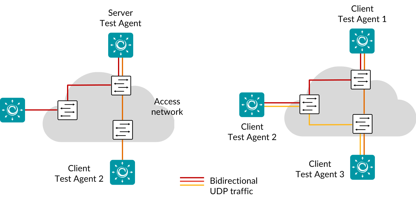
The pictures show hub-and spoke (left) or full-mesh (right) UDP traffic generation between two or more Test Agents for measuring link performance:
Running a UDP task will help you understand if your network is good enough for quality-demanding services such as client–server applications and videoconferencing.
When a UDP task starts, the Test Agents will generate traffic at the rate you specify. The rate is the Layer 2 Ethernet rate, also known as the Committed Information Rate (CIR). It includes the Ethernet headers with the CRC checksum but not the Frame Gap, Preamble, or Start of Frame Delimiter. The UDP flow sent by the sender Test Agent includes timestamps and sequence numbers, so that the receiving Test Agent can calculate one-way delay, jitter, packet loss, and packet misorderings.
Examples of network requirements:
Videoconferencing: Loss < 1%, jitter < 30 ms, one-way delay < 150 ms
Client–server: Loss < 2%, one-way delay < 100 ms
Such requirements can be immediately expressed as thresholds, set individually for each UDP task.
This task works with both IPv4 and IPv6.
Prerequisites
To run UDP measurements you need to have at least two Test Agents installed. If you haven’t already done the installation, consult the installation guides found here.
Then add a UDP task to your test or monitor and fill in the mandatory parameters below:
Parameters
See the common parameters page for the following:
Parameters that are set on the test step level: Duration, Fail threshold, and Wait for ready.
SLA thresholds for monitors: SLA Good and SLA Acceptable.
Advanced settings common to all test tasks: Delayed start.
General
Setup type: Select how to set up the measurement: “Client-Server” or “Full-Mesh”.
When Client-Server is selected, certain parameters take an Up/Down prefix, whereas for Full-Mesh this prefix is absent. Default: Client-Server.Server: Test Agent interface that is going to act as server.
If a NAT router or firewall is present, the server must be located on the outer (public) side.Clients: Test Agent interfaces exchanging UDP traffic with the server.
The clients can be placed behind NAT, since traffic will be initiated from the clients to the server.Number of flows: Number of UDP flows.
If more than one flows is specified, the Client port setting is ignored and all client ports will be ephemeral. Min: 1. Max: 64. Default: 1.
Note
Even if multiple flows are used, a single set of statistics is shown with aggregate values picked for each parameter: average rate, average loss, sum of misorderings, minimum delay, average delay, maximum delay, maximum jitter, and sum of ES.
Note
Using multiple flows may lower loss figures. This is because distributing data across several flows may lead to fewer misorderings (misordered packets are counted as lost). For example, suppose we are using a single flow and packets arrive in the order 0, 2, 1, 3, 4. This sequence contains one misordering. Now suppose that we instead use two flows with packets 0, 1, 4 arriving in one flow and packets 2, 3 in the other. In this case we have no misorderings. The same tendency towards elimination of misorderings will prevail generally.
Direction: One of: Down (from server to clients), Up (from clients to server), or Bidirectional (in both directions at the same time).
Up rate (Mbit/s): Client-to-server target data rate.
Min: 0.01 Mbit/s. Max: 1,000 Gbit/s.Down rate (Mbit/s): Server-to-client target data rate.
Min: 0.01 Mbit/s. Max: 1,000 Gbit/s.Rate (Mbit/s): Client-to-client target data rate when running in Full-mesh.
Min: 0.01 Mbit/s. Max: 1,000 Gbit/s.Port: UDP server port to which clients will send traffic.
Range: 1 … 65535. Default: 5000.Client port: (Optional) UDP client port from which clients will send traffic.
If this is omitted, the client will select a port. Range: 1 … 65535.
Thresholds for errored seconds (ES)
Up/Down loss (%): Packet loss threshold for triggering an errored second.
If the loss exceeds this value during one second, an ES will be indicated. Min: 0%. Max: 100%. Default: 0%.Up/Down jitter (ms): Jitter threshold for triggering an errored second.
If the jitter (delay variation) between server and reflector exceeds this value during one second, an ES will be indicated. Min: 1 ms. Max: 1000 ms. No default.Up/Down delay (ms): One-way delay threshold for triggering an errored second.
If the delay between server and reflector exceeds this value during one second, an ES will be indicated. Min: 1 ms. Max: 1000 ms. No default.Up/Down expected DSCP:
The expected Differentiated Services Code Point or IP Precedence that the IP packets will have at the receiving side. If the received DSCP value does not match, an ES will be indicated. By default, no DSCP validation is done (------selected in drop-down box).
Thresholds for severely errored seconds (SES)
Up/Down loss (%): Packet loss threshold for triggering a severely errored second. Min: 0%. No default.
Up/Down jitter (ms): Jitter (delay variation) threshold for triggering a severely errored second. Min: 0 ms. No default.
Up/Down delay (ms): One-way delay threshold for triggering a severely errored second. Min: 0 ms. No default.
Advanced
Don’t fragment datagram: Controls whether the datagram that exceeds the MTU is allowed to be fragmented. Be aware that enabling fragmentation (by specifying the “No” option) may cause performance degradation both in the network and in the sending or receiving Test Agents.
Note
This setting has no effect on IPv6 packets.
Up/Down Ethernet frame size (bytes): Size of Layer 2 Ethernet frame for the flow.
See this page. Min: 64 bytes for IPv4; 84 bytes for IPv6. Max: 9018 bytes. Default: 1518 bytes.Up/Down DSCP/IPP: The Differentiated Services Code Point or IP Precedence to be used in IP packet headers.
See this page. The available choices are listed in the drop-down box. Default: “0 / IPP 0”.Up/Down VLAN priority (PCP): The Priority Code Point to be used in the VLAN header.
See this page. Range: 0 … 7. Default: 0. Note: When a Test Agent Application attempts to configure PCP settings in outgoing IP packets, it cannot be guaranteed that the settings are indeed carried through. This is because the Test Agent Application does not control the host it is running on and its interface configurations.Socket send buffer (bytes): Send socket buffer (in bytes) used for the flow.
This is used by the kernel to temporarily store packets before sending. Streams with higher rate need a larger buffer. Optional. Min: 2048 bytes. Max: 10,000,000 bytes. Default: By default this field is left blank. Routing Active Testing will then calculate the buffer size based on rate and Ethernet frame size. Example: For a 10 Mbit/s flow with Ethernet frame size 1518 bytes, a send buffer of size 14,544 bytes is used by default.Socket receive buffer (bytes): Receive socket buffer (in bytes) used for the flow.
This buffer is used by the kernel to temporarily store incoming packets. Streams with higher rate need a larger buffer. The socket buffer also limits the burst that the receiver is able to receive without packet loss. Optional. Min: 2048 bytes. Max: 10,000,000 bytes. Default: By default this field is left blank. Routing Active Testing will then calculate the buffer size based on rate and Ethernet frame size. Example: For a 10 Mbit/s flow with Ethernet frame size 1518 bytes, a receive buffer of size 95,312 bytes is used by default.
Result metrics
Rate (Mbit/s): Ethernet rate of the UDP flow.
Loss (%): Packet loss in percent.
Misordered (packets): Number of misordered packets.
Delay min (ms): Minimum one-way delay.
Delay average (ms): Average one-way delay.
Delay max (ms): Maximum one-way delay.
Note
The one-way delay metrics are only reported if certain requirements on NTP clock synchronization are met. Read more here.
Jitter (ms): Jitter (delay variation).
Received packets (packets): Number of received packets.
Lost packets (packets): Number of lost packets.
ES (%): Aggregated errored second (ES) percentage, taking into account all types of error.
ES loss (%): Errored second percentage for packet loss.
ES delay (%): Aggregated errored second percentage, taking into account delay and delay variation.
ES DSCP (%): Accumulated errored second percentage for DSCP.
Severely errored seconds (%): Aggregated severely errored second (SES) percentage, taking into account delay and delay variation.
Unavailable seconds (%): Unavailable second (UAS) percentage.
SLA: Service level agreement fulfillment: equal to (100 – ES) %.