Installing Test Agent Appliance on a PC Engines APU2 hardware server
Introduction
This page explains how to build a Routing Active Testing Test Agent on a PC Engines (► https://www.pcengines.ch) APU2 hardware server. The page lists the required hardware and describes how to assemble it and how to install the Test Agent software.
A quick summary of the procedure is as follows:
Get the hardware components.
Assemble the hardware components.
Install the Test Agent software.
Note
The procedure given here must be followed strictly; otherwise, errors may result.
Step 1: Obtaining the hardware components
The hardware server to be built is PC Engines APU2.
The hardware consists of the following components (auxiliary items such as screws and thermal paste are left out of the tables). Order the components from your preferred hardware supplier.
Required components
These components make up the basic APU2 hardware server.
Qty |
Component |
Brand |
Model/Version |
|---|---|---|---|
1 |
System board |
PC Engines |
apu2e2 1 |
1 |
Enclosure |
PC Engines |
case1d2u |
1 |
Power brick adapter |
PC Engines |
ac12veur3 (EU), ac12vus2 (US), ac12vuk2 (UK) |
1 |
SSD |
PC Engines |
msata16g: SSD M-Sata 16GB MLC, Phison S11 controller (for APU) |
- 1
Note on naming syntax: (a) “apu2” is the board and product name; (b) “e” is the revision; (c) “2” indicates the amount of RAM used.
Optional components
Wi-Fi card and antenna
Qty |
Component |
Brand |
Model/Version |
|---|---|---|---|
1 |
Wi-Fi modem |
Intel |
Intel Dual Band Wireless-AC 8265, model 8265 NGWMG |
1 |
Adapter |
(generic component) |
M.2 2230 to MiniPCIe adapter |
1 |
Antenna cable |
(generic component) |
MHF4 to RP-SMA (female), 4 or 5 inches (10 to 11 cm) |
1 |
Antenna |
(generic component) |
Wi-Fi antenna, MHF4 2.4/5g (20 cm) |
Step 2: Assembling the hardware
Necessary tools: Phillips-head and flat-head screwdrivers, scissors, tweezers.
Rip off the head spreader kit from the box and open it.
There is one aluminum heat spreader in the bag and two blue heat conductive pads. We will need only one heat conductive pad for the assembly. Keep the other one for future use.
Open the chassis. You should find a small bag inside the chassis containing eight screws, two plugs and four rubber legs.
Make sure to use the four bigger screws for the board and the four smaller ones for the chassis.
The heat spreader should be placed 35 mm from the left and 10 mm from the bottom. (In the video, a special fixture is used to achieve precise placement of the heat spreader. This item is not mandatory but is recommended if you are building a large batch. It can be purchased at the PC Engines web store. Use a ruler if you do not have the fixture.)
Take the board out of the bag and remove the two hex screws from the serial port. If you do not have a hex bit, use your fingers and/or pliers.
Turn the board upside down and place it on the bubble foil for protection.
There are two heat conductive pads on the strip. We will need only one.
Peel the blue foil from one side and place the pad on the CPU. Use tweezers to peel the foil from the other side of the pad.
Now it is time to mount the board into the chassis. Make sure that the conductive pad is placed firmly against the heat spreader.
Use the four larger screws to fasten the board to the chassis. Use a Phillips-head screwdriver (the one with the cross). The two screws near the connector panel are somewhat tricky, because they need to be inserted into a very narrow space.
Install the two hex screws, one on each side of the serial port.
Install the SSD into the mSata slot. There are three slots, but the SSD will work only in the mSata slot. The mSata slot is the one to the right on the board (with the connector panel facing upwards).
Push the drive into the slot at an angle, and then down. The drive should clip in.
Make sure that the two metal latches hold the SSD firmly in place. Use a toothpick or screwdriver to bend them. If the SSD is not firmly placed, it may fall out.
If you want to install a Wi-Fi card, do so now. Follow the installation instructions for that component below.
Now close the chassis using the four small screws.
There are two small plugs to plug the antenna holes. If you have not installed Wi-Fi on your system, install these plugs.
If you do not have a wall mount, you can install the four rubber legs that come with the chassis.
Step 2a: Installing a Wi-Fi card and antenna
Connect the Intel Wi-Fi card to the M2 adapter.
Attach the M2 adapter with the Wi-Fi card on it to the slot farthest from the mSata slot.
Gently connect the antenna cables to the Wi-Fi card module.
Slide the other end of each cable (the rubber antenna connector) through the case lid.
Tighten the nut from the outside of the lid to firmly fasten the rubber antenna connector onto it.
Screw the rubber antennas onto their respective connectors.
Step 3: Installing the Test Agent
Prerequisites
In this step you may need to access the BIOS on the PC Engines server. To this end, you need to connect to the server via a serial interface, so you require:
An RS-232-to-USB adapter.
A terminal emulator such as PuTTY (for Windows) or Terminal (for macOS).
The bit rate 38400 bit/s is required when first connecting to the PC Engines server.
In PuTTY, set the bit rate under Connection > Serial > Speed (baud).
In Terminal as well as in Linux, use the
cucommand with the syntax
cu -l /dev/<serial device to be used> -s 38400
Instructions
On a PC with internet access, log in to your account on your Routing Active Testing Control Center server.
In the left-hand pane, click Test Agents.
Click the Download button in the top right corner.
Click the link “RAW disk image (.img.gz)” to download that Test Agent disk image.
The next step is to write the disk image to a USB memory stick using the Etcher utility (which exists in Windows, macOS, and Linux versions).
Download the appropriate version of Etcher from ► https://etcher.io and install it.
Insert a USB memory stick with at least 4 GB of free space into your PC.
Open Etcher, and from your hard disk select the Test Agent disk image (netrounds-test-agent_<version number>.img.gz).
Select the USB memory stick in order to write the disk image to it.
Review your selections and click Flash!
Once you have burned the Test Agent disk image to the USB memory, insert it into a USB port on the PC Engines hardware server.
The BIOS will by default boot from USB. However, if the BIOS boot priority has been changed, you need to access the BIOS and restore the default settings. This is described in the steps below.
Connect to the PC Engines hardware server using a terminal emulator (see Prerequisites above). Note that the bit rate 38400 bit/s must be used in this step.
Before accessing the BIOS, change the bit rate to 115200 bit/s.
Access the BIOS boot menu, and make sure the USB memory comes before the hard disk in the boot sequence.
Change the bit rate back to 38400 bit/s.
Select USB boot from the BIOS boot menu.
The boot process takes about 20 seconds. When the login prompt is shown, log in as user “admin” with password “admin”.
Go to Utilities.
Select Install to disk.
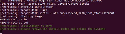
When the procedure has finished, the screen will look like this:
Power down the PC Engines hardware server.
Remove the USB memory stick, then boot up the server without the USB memory stick connected and confirm that the Test Agent is installed.