Installing Test Agent Appliance on a Supermicro hardware server
Introduction
This page explains how to build a Routing Active Testing Test Agent on a Supermicro (► https://www.supermicro.com) hardware server. The document lists the required hardware as well as some optional expansions, and describes how to install the BIOS and the Test Agent software.
A quick summary of the procedure is as follows:
Get the hardware components.
Assemble the hardware components.
Flash the BIOS.
Install the Test Agent software.
(If applicable:) Install optional hardware components.
Note
The procedure given here must be followed strictly; otherwise, errors may result. For example, if you install an extra network interface card before installing the Test Agent software, interface names may be assigned randomly to ports.
Step 1: Obtaining the hardware components
The hardware consists of the following components (auxiliary items such as screws and thermal paste are left out of the tables). Order the components from your preferred hardware supplier.
Required components
These components make up the basic Supermicro hardware server.
Qty |
Component |
Brand |
Model/Version |
|---|---|---|---|
1 |
Motherboard |
Supermicro |
X11SSH-LN4F |
1 |
BIOS |
Supermicro |
2.0b |
1 |
CPU |
Intel |
Intel Xenon E3-1240v6 3.7/4.1 GHz Quadcore HT, 8 MB |
Part number: BX80677E31240V6 |
|||
1 |
Heat sink |
Supermicro |
SNK-P0046P |
2 |
RAM |
Kingston |
Kingston 4 GB DDR4 ECC 2400 MHz UDIM |
Part number: KVR24E17S8/4 |
|||
1 |
HDD |
Supermicro |
SDD-DM016 |
1 |
Power supply |
Supermicro |
PWS-203-1h |
1 |
Chassis |
Supermicro |
Superchassis 510-203B |
2 |
Fan |
Nidec |
W40S-A5 |
Required configuration
The IPMI port must be sealed. IPMI must be turned off for the LAN ports.
Auto power-on must be enabled in BIOS.
PXE boot must be disabled.
Optional components
You can install either of the network interface cards listed in this section (but not both).
10 Gbit network interface card
Qty |
Component |
Brand |
PID |
Model/Version |
|---|---|---|---|---|
1 |
4-port 10 Gbit network interface card |
Supermicro |
HW-NIC20-P |
Supermicro Intel X710 4-port SFP+ 10GbE PCIe 3.0 x8 LP AOC-STG-i4S |
1 |
Network riser |
Supermicro |
RSC RR1UE16 |
SFP+ transceivers
Qty |
Component |
Brand |
PID |
Model/Version |
|---|---|---|---|---|
1 |
SFP+ transceiver |
Intel |
HW-SFP+L-P |
Intel SFP+ LR Optics 10GBASE-LR/1000BASE-LX |
1 |
SFP+ transceiver |
Intel |
HW-SFP+S-P |
Intel SFP+ SR Optics 10GBASE-SR/1000BASE-SX |
4-port 1 Gbit network interface card
Qty |
Component |
Brand |
PID |
Model/Version |
|---|---|---|---|---|
1 |
4-port 1 Gbit network interface card |
Supermicro |
HW-NIC1-P |
Supermicro Intel AOC-SGP-I4 |
1 |
Network riser |
Supermicro |
RSC RR1UE16 |
Step 2: Assembling the hardware
How to assemble the hardware components is not described in detail here and is assumed to be known. However, note the following:
Thermal paste must be applied between the CPU and heat sink during installation of the CPU.
Any expansions must be installed at the end of the procedure (see Step 5).
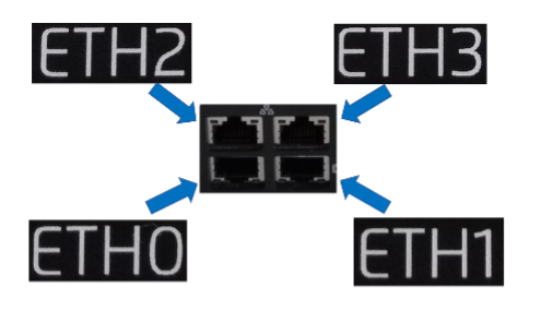
The assignment of interfaces to ports appears from Figure 1. Label the ports according to this image.
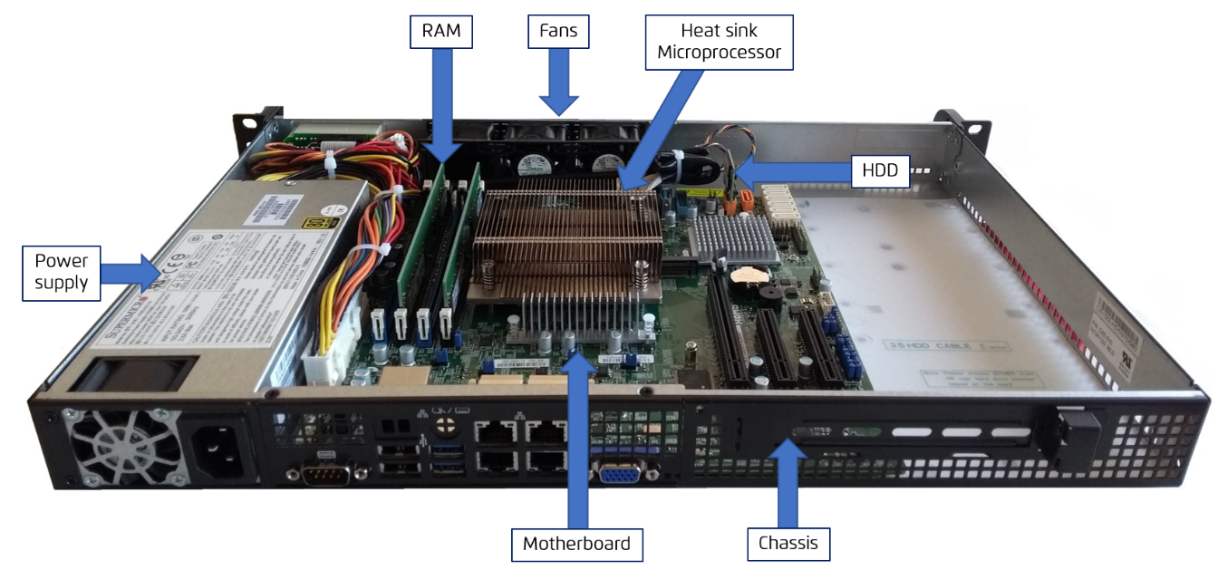
The image below shows a Supermicro hardware server with all components in Step 1 installed.
Step 3: Installing the correct BIOS version
The BIOS version to be used on the Supermicro X11SSH-LN4F motherboard is version 2.0b. This is the BIOS version used in testing Routing Active Testing, so it is necessary to use this version in order to ensure performance. Please contact Juniper Networks in order to obtain the correct BIOS.
Then do as follows to update the BIOS to the correct version:
The
Readme.txtfile provided by Supermicro has instructions on how to create a bootable FreeDOS USB. Follow these instructions.Once this is done, here is how to update the BIOS (for the version 2.0b):
Start up the Supermicro with
a keyboard plugged in
a bootable USB with BIOS (created in Step 1) connected
a VGA monitor connected
When the “Supermicro” screen shows up, press F11 to enter the booting menu.
Select the USB memory stick (usually identified here by the USB vendor’s name).
Select Default (the only option available).
Select “FreeDOS Live CD only”.
Execute the following commands to see the correct file to use:
C:                       // (Press Enter)
dir                      // Displays files
flash.bat X11SSH7.727    // Flashes the BIOS for this specific model
When the
flash.batcommand finishes, it displays the following output:
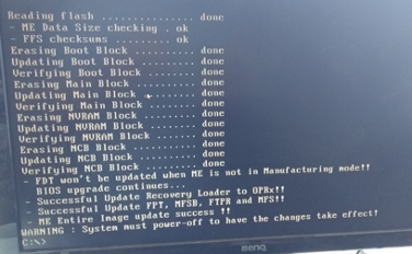
After the flashing procedure, the Supermicro server may restart twice before starting up as normal.
Step 4: Installing the Test Agent
On a PC with internet access, log in to your account on your Routing Active Testing Control Center server.
In the left-hand pane, click Test Agents.
Click the Download button in the top right corner.
Click the link “RAW disk image (.img.gz)” to download that Test Agent disk image.
The next step is to write the disk image to a USB memory stick using the Etcher utility (which exists in Windows, macOS, and Linux versions).
Download the appropriate version of Etcher from ► https://etcher.io and install it.
Insert a USB memory stick with at least 4 GB of free space into your PC.
Open Etcher, and from your hard drive select the Test Agent disk image (
netrounds-test-agent_<version number>.img.gz).Select the USB memory stick in order to write the disk image to it.
Review your selections and click Flash!
Once you have burned the Test Agent disk image to the USB memory, insert it into a USB port on the Supermicro hardware server.
Access the BIOS boot menu.
Make sure the USB memory comes before the hard drive in the boot sequence.
Select USB boot from the BIOS boot menu.
The boot process takes about 20 seconds. When the login prompt is shown, log in as user “admin” with password “admin”.
Go to Utilities.
Select Install to disk.
When the procedure has finished, the screen will look like this:
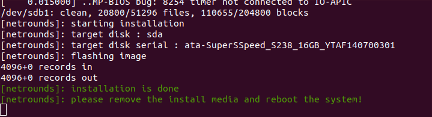
Power down the Supermicro hardware server.
Remove the USB memory stick, then boot up the server without the USB memory stick connected and confirm that the Test Agent is installed.
Step 5: Installing optional components
Once the Test Agent software is installed, you can install one of the hardware expansions (10 Gbit network interface card, 4-port 1 Gbit network interface card).
Note
This must be left until after the Test Agent software has been installed. If you install an extra network interface card before the Test Agent software, interface names may be randomly assigned to ports (for example, “eth0” to a port on the motherboard, “eth1” to a port on the extra card, etc.).
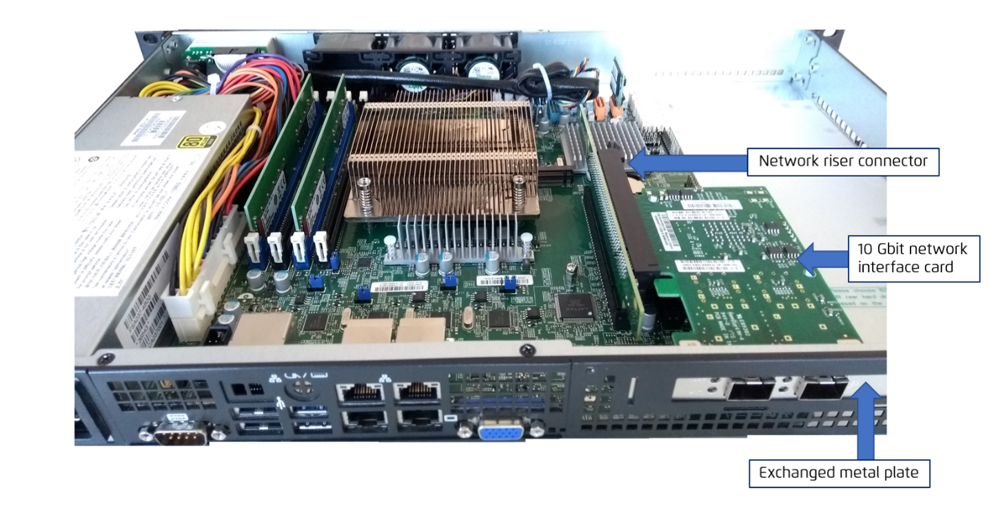
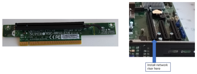
If you want to install an extra network interface card, you also need to install a network riser in the slot indicated in the following image:
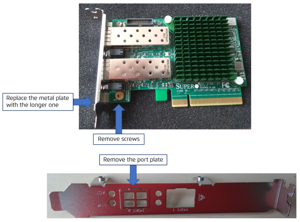
For the network interface card itself, you need to exchange the metal plate at the front for a longer one as shown in the figure below:
Finally, this picture shows a Supermicro hardware server with network riser and 10 Gbit network interface card mounted: