UDP loopback
This task pushes UDP packets from a Test Agent towards a network device (router/switch) acting as reflector. The reflector device loops each UDP packet back to the Test Agent.

The primary purpose of the UDP loopback task is to achieve very high data throughput in testing. To enable this, the reflector device needs to be configured in either of two special ways so that any UDP traffic can be looped back in hardware (in the forwarding plane). The possibilities are described below.
Note
Either of these special reflector configurations is required for the UDP loopback task to work.
With such a configuration in place, the reflector device does not create a new packet to send back; rather, it forwards the same packet it has received back to the Test Agent originating it. This is different from the procedures for TWAMP or UDP echo, where the reflector does create a new packet which it sends back to the Test Agent.
This task works with IPv4 as well as IPv6.
Prerequisites
To perform UDP loopback measurements, you need to install at least one Test Agent. For guidance on how to deploy a new Test Agent, see the installation guides found here.
You also need to have a device (router or switch) available in your network that can serve as reflector of UDP packets.
Reflector configuration
Either IP loopback configuration or NAT (network address translation) is required on the reflector device in order for that device to reflect the UDP traffic back to the Test Agent.
The use of Cisco equipment is assumed in the description that follows. Equipment from other manufacturers needs to be configured correspondingly.
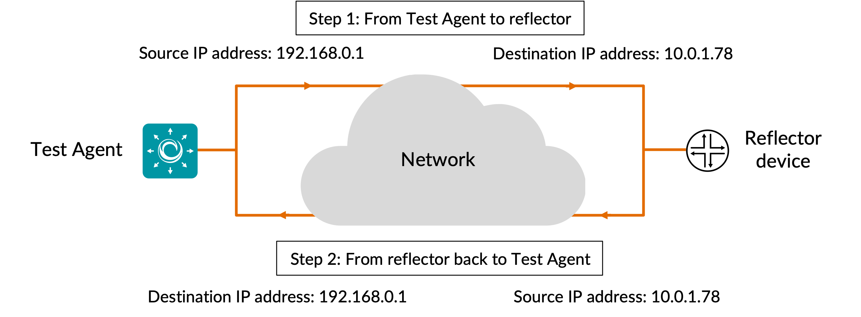
Option 1: IP loopback configuration
Many types of network devices, such as routers, switches and smart SFPs, can be configured to receive an IP packet with a combination of source and destination IP address, switch the two addresses, and send back the modified IP packet.
The diagram below illustrates how the IP addressing in the packet changes in the course of transferring the packet from the Test Agent to the reflector device and back again.
In a Cisco router, configure reflector as follows:
! Specify the SLA ID to start the IP SLA session.
ip sla 1

! Specify the service performance type as IP and the destination IP address.
! Specify the target for the SLA session. The options are: service instance, interface,
! vrf, and bridge-domain.
service-performance type ip dest-ip-addr 10.0.1.78 interface gi0/0/0 service instance 1

! Specify the number of interactions and the delay between iterations.
frequency iteration 1 delay 1

! Configure the loopback direction.
loopback direction internal

! Specify the packet profile, defining the packets to be generated.
profile packet
! Specify the source IP address.
source-ip-addr 192.168.0.1
! Specify the VLAN ID that is populated in the outer VLAN tag of the packet.
outer-vlan 301
! Specify the period of time for which to send packets.
duration time 30000
In a Juniper router, configure reflector as follows:
# Start configuration editing
edit
set services monitoring rfc2544 tests test-name ref-ip mode reflect
set services monitoring rfc2544 tests test-name ref-ip family inet
# Specify the target inteface
set services monitoring rfc2544 tests test-name ref-ip test-interface et-0/0/0.0
# Specify the UDP port of the destination to be used in the UDP header for the generated frames
set services monitoring rfc2544 tests test-name ref-ip source-udp-port 7777
# Specify the UDP port of the source to be used in the UDP header for the generated frames
set services monitoring rfc2544 tests test-name ref-ip destination-udp-port 7777
# Specify the destination IPv4 address to be used in generated test frames
set services monitoring rfc2544 tests test-name ref-ip destination-ipv4-address 192.168.0.1
# Specify the source IPv4 address to be used in generated test frames
set services monitoring rfc2544 tests test-name ref-ip source-ipv4-address 10.0.1.78
set services monitoring rfc2544 tests test-name ref-ip disable-signature-check
commit
# Exit from editing
exit
# Start the test
test services monitoring rfc2544 test ref-ip start
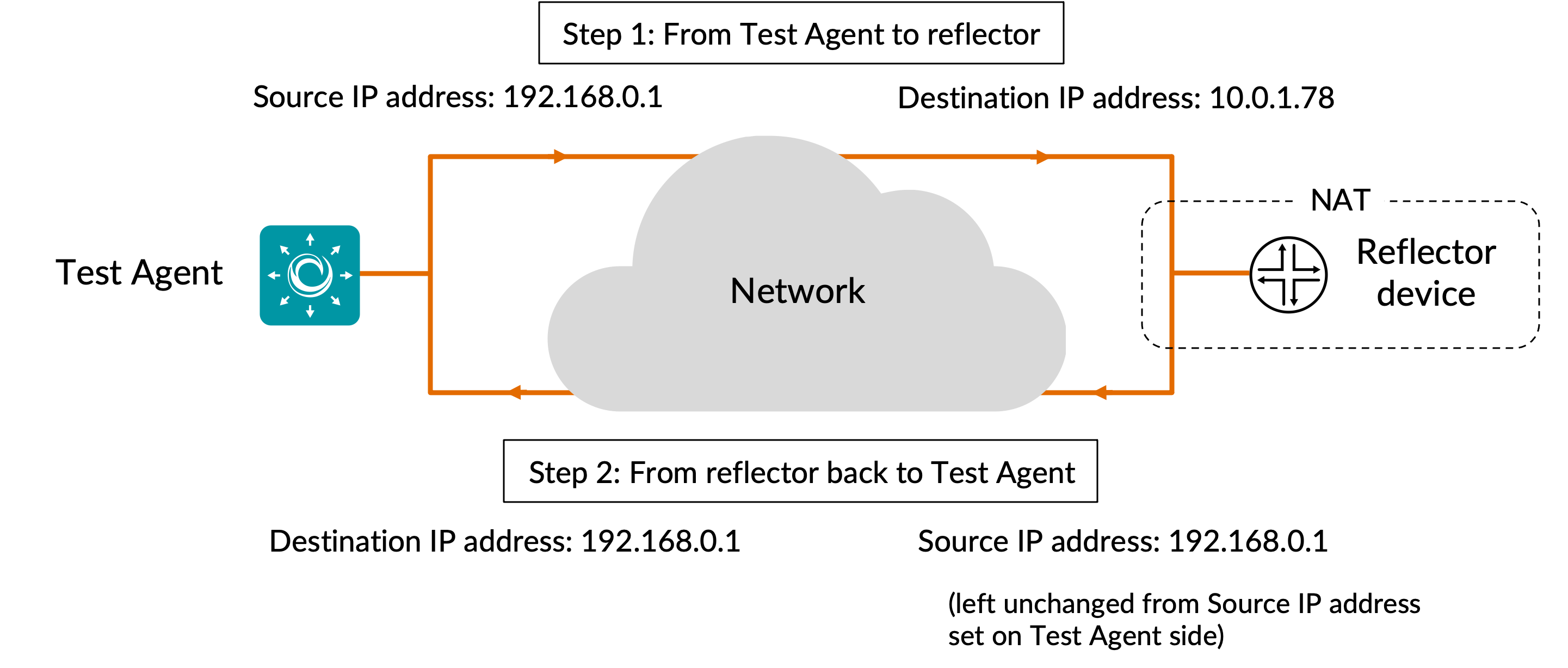
Option 2: NAT configuration
In a Cisco router, the network address translation takes place prior to packet forwarding. The WAN interface where the traffic enters the router (GigabitEthernet X in the example below) needs to be defined as the NAT “outside” interface, and a loopback interface (loopback Y below) needs to be defined as the NAT “inside” interface. Network address translation is then set up using the ip nat inside command.
With this NAT setup, the following happens:
The source IP address in the packet sent from Test Agent to reflector is retained as source IP address when the packet is reflected back to the Test Agent.
The destination IP address in the packet sent from Test Agent to reflector is exchanged (according to the IP NAT table) for the Test Agent IP address when the packet is reflected back to the Test Agent.
In the reflection step, therefore, the source and destination addresses are the same.
The diagram that follows illustrates how the IP addressing in the packet changes in the course of transferring the packet from the Test Agent to the reflector device and back again.
Below is shown how to do the NAT configuration, which is mandatory:
! Create a "loopback Y" interface with an IP address and define it as "inside".
! In the above example, this IP address is 10.0.1.78 (i.e. reflector address)
interface loopback Y
     ip add <loopback interface IP address> 255.255.255.255
     ip nat inside

! Define the WAN interface as "outside"
interface GigabitEthernet X
     ip nat outside

! Create a NAT entry which translates the loopback address into the Test Agent's IP address.
! This redirects traffic with the loopback address as destination to the Test Agent.
! In the above example, the Test Agent has IP address 192.168.0.1
ip nat inside source static <Test Agent IP address> <loopback interface IP address>
Routing configuration (always needed)
Routing configuration requirements are more variable, as explained further in the comments below. Announcing the loopback address in some way is however mandatory.
In the case of IP loopback, the loopback address is the IP address of the interface where the IP loopback functionality has been turned on.
In the NAT case, the loopback address is equal to the address of the loopback interface (named “Y” in the example above).
The configuration may look something like this:
! Tell the router how to send traffic to the Test Agent.
! This can be skipped if the Test Agent IP address is already available in routing tables.
! In the above example, <next-hop IP address> is "GigabitEthernet X"
ip route <Test Agent IP address> 255.255.255.255 <next-hop IP address>

! For the Test Agent to reach the loopback address, the latter must be announced in the
! routing. Below, this is done via BGP (Border Gateway Protocol).

! Enter into BGP configuration with relevant AS (autonomous system) number
router bgp <AS number>
     ! Add loopback address to BGP to have it announced via this protocol
     network <loopback interface IP address> mask 255.255.255.255
When done configuring the router, add a UDP loopback task to your test or monitor, and fill in the mandatory parameters as shown below.
Parameters
See the common parameters page for the following:
Parameters that are set on the test step level: Duration, Fail threshold, and Wait for ready.
SLA thresholds for monitors: SLA Good and SLA Acceptable.
Advanced settings common to all test tasks: Delayed start.
General
Sender: Test Agent interface that will act as sender (and receiver) of UDP packets.
Host: IP address of device acting as reflector.
This is the address of the “outside” interface referred to in the Reflector configuration section.UDP port: UDP destination port on reflector device. The same port will be used as source port on the Test Agent.
Note: This port must not be selected in any other test or monitor task using the same Test Agent interface. If you are setting up multiple UDP loopback tasks to run on the same Test Agent interface, use a different UDP port in each task.Rate (Mbit/s): Rate at which the sender will send Ethernet frames in Mbit/s.
The value is calculated based on packet rate and frame size. Each Ethernet packet contains one frame. Max: 10,000 Mbit/s. No default.Rate (packets/s): Number of Ethernet frames the sender will send each second.
Each Ethernet packet contains one frame. Minimum and maximum values correspond to those for Rate (Mbit/s) and depend on the Frame size setting. No default.Frame size (bytes): Size of Layer 2 Ethernet frame for the flow.
See this page. Min: 64 bytes for IPv4, 84 bytes for IPv6. Max: 9018 bytes. Default: 1518 bytes. If you change this setting, the Rate setting last edited will be kept constant, and the other will be adjusted automatically.
Changing one Rate parameter will cause the other to adjust automatically to agree with it.
Thresholds for errored seconds (ES)
Rate (Mbit/s): Ethernet rate threshold for triggering an errored second.
If the rate goes below this value during one second, an ES will be indicated. Max: 10,000 Mbit/s. No default.Loss (%): Round-trip packet loss threshold for triggering an errored second.
If the loss exceeds this value during one second, an ES will be indicated. Min: 0%. Max: 100%. Default: 0%.Delay (ms): Round-trip delay threshold for triggering an errored second.
If the round-trip delay exceeds this value during one second, an ES will be indicated. Min: 1 ms. Max: 1000 ms. No default.Delay variation (ms): Round-trip jitter threshold for triggering an errored second.
If the round-trip jitter (delay variation) exceeds this value during one second, an ES will be indicated. Min: 1 ms. Max: 1000 ms. No default.Expected DSCP:
The Differentiated Services Code Point or IP Precedence that IP packets are expected to have on being received from the reflector device. If the received DSCP value does not match this, an ES will be indicated. By default, no DSCP validation is done (------selected in drop-down box).
Thresholds for severely errored seconds (SES)
Loss (%): Packet loss threshold for triggering a severely errored second. Min: 0%. No default.
Delay (ms): Delay threshold for triggering a severely errored second. Min: 1 ms. No default.
Delay variation (ms): Delay variation threshold for triggering a severely errored second. Min: 1 ms. No default.
Advanced
DSCP: Differentiated Services Code Point or IP Precedence to be used in IP packet headers.
See this page. The available choices are listed in the drop-down box. Default: “0 / IPP 0”.VLAN priority (PCP): The Priority Code Point to be used in the VLAN header.
See this page. Min: 0. Max: 7. Default: 0.
Result metrics
Received packets: Number of Ethernet packets received.
Rate (Mbit/s): Received Ethernet packet rate.
Min round-trip delay (ms): Minimum round-trip delay.
Average round-trip delay (ms): Average round-trip delay.
Max round-trip delay (ms): Maximum round-trip delay.
Average round-trip DV (ms): Average round-trip delay variation.
Lost packets: Number of lost packets.
Loss (%): Packet loss in percent.
Misorders: Number of packet misorderings.
ES (%): Aggregated errored second (ES) percentage, taking into account all types of error.
ES rate (%): Accumulated errored second percentage for received rate.
ES loss (%): Accumulated errored second percentage for packet loss.
ES delay (%): Accumulated errored second percentage for round-trip delay.
ES delay variation (%): Accumulated errored second percentage for round-trip delay variation.
ES DSCP (%): Accumulated errored second percentage for DSCP.
SES (%): Aggregated severely errored second (SES) percentage, taking into account all types of error.
Unavailable seconds (%): Unavailable second (UAS) percentage.
SLA: Service level agreement fulfillment: equal to (100 – ES) %.