Test Agent interface configuration
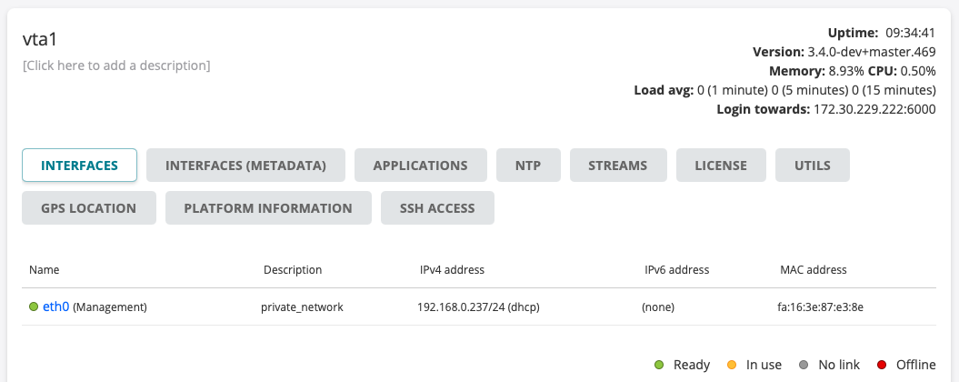
The Interfaces tab of the Test Agent configuration dialog lists the interfaces to the Test Agent.
Types of Test Agent interfaces
Test Agent interfaces are of one of the following kinds:
Physical: A “normal” physical network interface that exists in hardware in the Test Agent.
VLAN: A Virtual LAN interface which has a parent interface.
A VLAN interface is created on a parent interface as described here.Bridge: The “virtual interface” part of a network bridge. The bridge connects a set of “child” (bridged) interfaces.
A bridged interface cannot be the management interface, nor can it be used for NTP. Bridges are created as described here.Mobile: A special interface that uses a USB 4G dongle. Mobile interfaces have some special settings specific to the mobile network, but few other network-related settings since these are not exposed.
See this page.Wi-Fi: A special interface that uses a Wi-Fi card. Wi-Fi interfaces have some settings specific to the Wi-Fi network.
See this page.
In a virtual Test Agent running in a hypervisor, all interfaces are of course virtual. The assignment of interface names for a virtual Test Agent is described here.
Naming of Test Agent interfaces
For a Test Agent Application in an environment with multiple namespaces, interface names follow the syntax <namespace>/<interface>. For example, “ns1/eth0” means “interface eth0 in namespace ns1”. Read more about Test Agent Application namespace awareness here.
In other situations, interface names consist solely of an interface designation such as “eth0” or “wlan0”.
Status of Test Agent interfaces
The status of each interface is indicated by a colored dot to the left of the interface name.
|
Green: Online and ready, currently not in use |
|
Yellow: Online and currently in use |
|
Gray: No Ethernet link |
|
Red: Offline |
Properties of Test Agent interfaces
Provided that the Test Agent is not offline or shared, you can click each of its interfaces (for example, “eth0”) to display the configuration options for that interface. These include IP/MAC addresses, DHCP, VLANs, and bridges. A new tabbed dialog appears for the interface; its contents are gone through in the subsections that follow.
Note
If the Test Agent has a mobile interface, it is named “usb0”. This type of interface has a different set of configuration options, including mobile-specific ones. See Mobile interface configuration details.
For an introduction to using mobile interfaces, see also the page on mobile network measurements.
Status tab
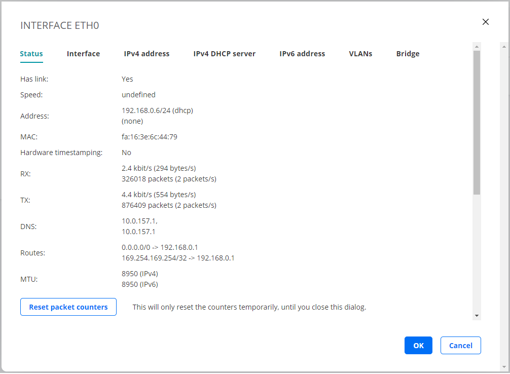
The Status tab of the interface configuration dialog shows read-only information: link status, interface, IP/MAC address, RX/TX data rates, DNS server IP address, and the routes for the interface. You can reset packet counters by clicking the Reset packet counters button.
Interface tab
On this tab you can configure the link properties of the interface.
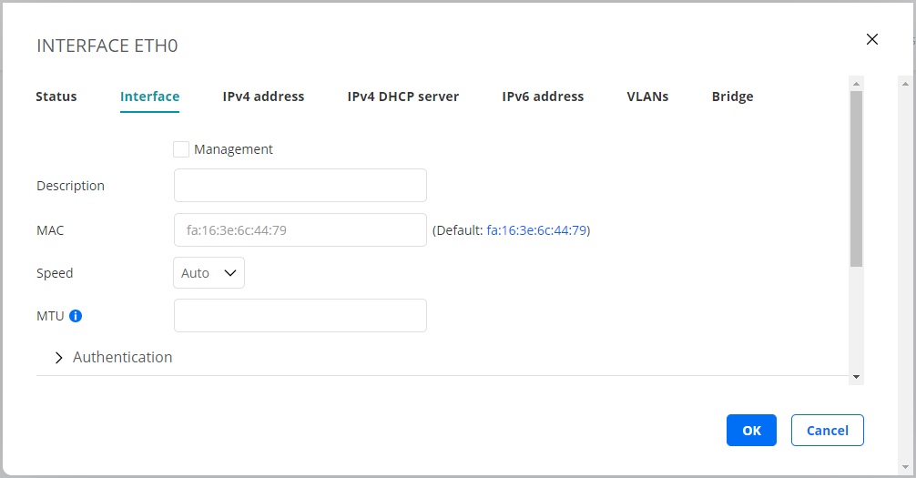
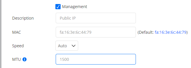
Management: Check the box if this interface is to be used as Routing Active Testing internal management interface for connection to the Routing Active Testing server. Management can be done over either IPv4 or IPv6. By default, “eth0” is selected as management interface. Note: Be careful when changing the management interface, as the Routing Active Testing server might lose contact with the Test Agent if you accidentally configure this interface incorrectly.
Description: Plain-text description of the interface.
MAC: Changeable MAC address. In the screenshot above, the MAC is changed to mimic a set-top box.
Speed: The link speed and duplex settings of the interface. Default: Auto.
MTU: The Maximum Transmission Unit size on the interface. Range: 1280 … 9216 bytes. Note: The MTU set here is only an initial value. Leaving this field empty means that the MTU will not be set. It may be changed at any time to a value specified in a DHCP lease or a Router Advertisement (RA).
Authentication
Here you can optionally set parameters for 802.1X authentication.
Authentication type: The 802.1X authentication type used in the network.
One of:EAP-TLS: Extensible Authentication Protocol - Transport Layer Security (EAP-TLS), an IETF open standard that uses the Transport Layer Security (TLS) protocol.
Defined in ► IETF RFC 5216. EAP-TLS is the original, standard wireless LAN EAP authentication protocol.EAP-TTLS/MSCHAPv2: EAP Tunneled Transport Layer Security (EAP-TTLS), an EAP protocol that extends TLS.
Defined in ► IETF RFC 5281.PEAPv0/EAP-MSCHAPv2: Protected EAP, a protocol that encapsulates EAP within a potentially encrypted and authenticated Transport Layer Security (TLS) tunnel.
None: Open network, no security.
The parameters vary depending on the choice made under Authentication type. The following parameters occur:
Anonymous identity: Used in EAP-TTLS and PEAP to allow the authenticator to choose the correct authentication server to process the credentials.
Identity: The client’s identity in the network.
Password: The client’s password for the network.
CA certificate: Certificate Authority certificate, PEM encoded.
The input takes the following form:-----BEGIN CERTIFICATE----- (base 64 encoded DER) -----END CERTIFICATE-----
Client certificate: Client certificate, PEM encoded.
The input takes the following form:-----BEGIN CERTIFICATE----- (base 64 encoded DER) -----END CERTIFICATE-----
Private key: Unencrypted key.
The input takes the following form:-----BEGIN PRIVATE KEY----- (base 64 encoded DER) -----END PRIVATE KEY-----
IPv4 address tab
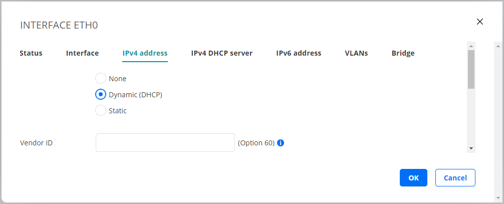
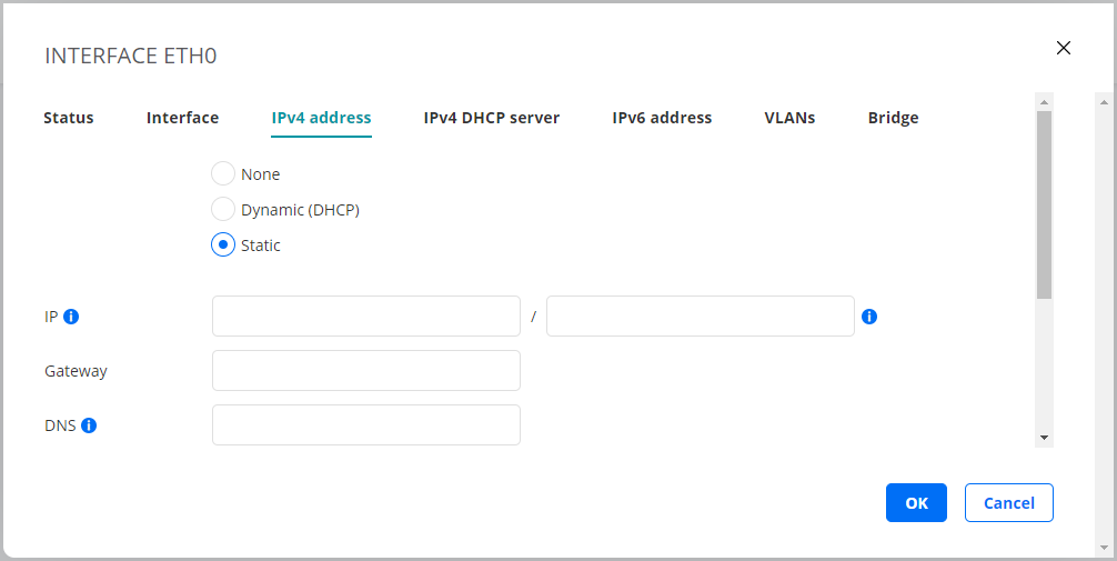
On this tab you configure IPv4 address assignment for the interface. The options are None, Dynamic (DHCP), and Static.
Dynamic (DHCP)
An IPv4 address is assigned by a DHCP server.
Vendor ID (Option 60): This option is used to optionally identify the vendor type and configuration of a DHCP client.
Vendors may choose to define specific vendor class identifiers to convey particular configuration or other identification information about a client. For example, the identifier may encode the client’s hardware configuration.
See ► IETF RFC 2132 for details.
Static
A static IPv4 address is assigned to the Test Agent.
IP: The IP address is specified in the IP/prefix length format. Example: “192.168.1.5/24”.
IPv4 addresses can be specified using two different notations:
192.168.0.5/255.255.255.0(Netmask)192.168.0.5/24(Prefix length)
For consistency among all IP addresses, Routing Active Testing expects the prefix length notation. For example, prefix length /24 is the same as 255.255.255.0. Full information is given in the following conversion table:
Netmask |
Prefix length |
Netmask |
Prefix length |
|---|---|---|---|
255.255.255.255 |
/32 |
255.254.0.0 |
/15 |
255.255.255.254 |
/31 |
255.252.0.0 |
/14 |
255.255.255.252 |
/30 |
255.248.0.0 |
/13 |
255.255.255.248 |
/29 |
255.240.0.0 |
/12 |
255.255.255.240 |
/28 |
255.224.0.0 |
/11 |
255.255.255.224 |
/27 |
255.192.0.0 |
/10 |
255.255.255.192 |
/26 |
255.128.0.0 |
/9 |
255.255.255.128 |
/25 |
255.0.0.0 |
/8 (Class A) |
255.255.255.0 |
/24 (Class C) |
254.0.0.0 |
/7 |
255.255.254.0 |
/23 |
252.0.0.0 |
/6 |
255.255.252.0 |
/22 |
248.0.0.0 |
/5 |
255.255.248.0 |
/21 |
240.0.0.0 |
/4 |
255.255.240.0 |
/20 |
224.0.0.0 |
/3 |
255.255.224.0 |
/19 |
192.0.0.0 |
/2 |
255.255.192.0 |
/18 |
128.0.0.0 |
/1 |
255.255.128.0 |
/17 |
0.0.0.0 |
/0 |
255.255.0.0 |
/16 (Class B) |
Gateway: The IP address of the default gateway in your network.
DNS: DNS server address(es). Multiple servers can be specified using a comma-separated list.
At least one DNS server is required for the Test Agent management interface as the Test Agent resolves the Routing Active Testing server host name (for the public cloud server, https://login.paa.juniper.net) in order to set up the encrypted management connection to the Routing Active Testing server. For an on-premise Routing Active Testing server with a static IP address, no DNS lookup is of course needed. For other interfaces, a DNS server is required only for certain tests such as HTTP, DNS and Ping, again if the target address is entered as a host name.
IPv4 DHCP server tab
On this tab you can activate a DHCP server on the interface. To use the function you must have the interface configured with a static IPv4 address.
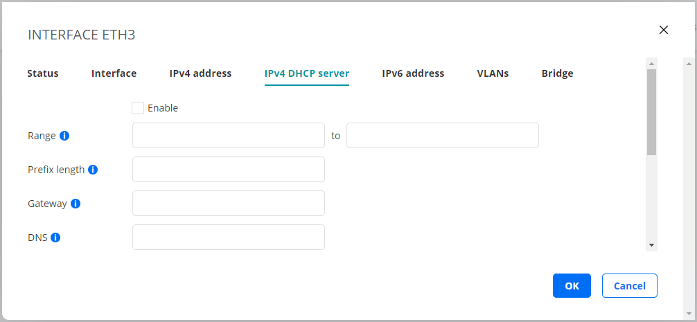
Enable: Check this box to enable the DHCP server.
Range: The IP address interval from which the DHCP server will assign addresses to clients.
Prefix length: The length of the address prefix. See the IP address description above for more information about the prefix length format.
Gateway: The default gateway to send to clients.
DNS: The DNS server to send to clients.
IPv6 address tab
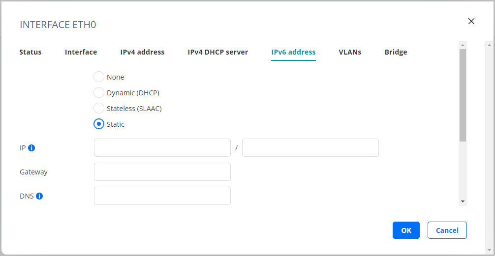
This tab is where you configure IPv6 address assignment for the interface. The options are None, Dynamic (DHCP), Stateless (SLAAC), and Static.
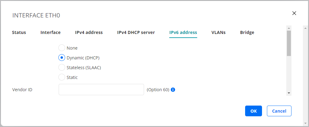
Dynamic (DHCP)
An IPv6 address is assigned by a DHCP server.
Vendor ID (Option 60): This option is used to optionally identify the vendor type and configuration of a DHCP client.
Vendors may choose to define specific vendor class identifiers to convey particular configuration or other identification information about a client. For example, the identifier may encode the client’s hardware configuration.
See ► IETF RFC 2132 for details.
Stateless (SLAAC)
The Test Agent self-assigns an IPv6 address by means of Stateless Address Autoconfiguration (SLAAC).
SLAAC is described in ► IETF RFC 4862.
DNS: DNS server address(es). Multiple servers can be specified using a comma-separated list.
Static
A static IPv6 address is assigned to the Test Agent.
IP: The IPv6 address is specified in the IP/prefix length format. The format used by |paa-product| for IPv6 addresses is “0123::4567:89ab:cdef:0123/64”.
For IPv6 addresses only the prefix length notation is available, since typing 128-bit netmasks would be very tedious. You thus need to type the IPv6 address in full or collapsed form followed by the prefix length.
Note that the deprecated site-local IPv6 addresses cannot be used. These have the unicast prefix “fec0::/10”. See ► IETF RFC 3879 for further information.
Gateway: The IPv6 address of the default gateway in your network.
DNS: DNS server address(es). Multiple servers can be specified using a comma-separated list.
VLANs tab
On this tab you can create VLANs on an interface. Test Agents support VLAN according to IEEE 802.1Q. The screenshot shows an example where VLANs can be added on the physical interface “eth0”.

If a bridge exists, you can add VLANs on top of that bridge. Type the VLAN identifier in the box, then click the Add button.

On the top-level Interfaces tab, VLANs will appear as shown below:
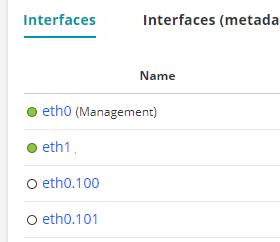
The MAC address of a VLAN is by default inherited from its parent interface. You can manually set a different MAC address for the VLAN on the Interface tab of its properties dialog. Click the VLAN link to access that dialog.
Bridge tab
On this tab you can add a bridge to and remove a bridge from an interface.

To a bridge one or more interfaces can be connected, as shown in the screenshot below. Use the left and right arrow buttons to configure which interfaces should be joined by the bridge.
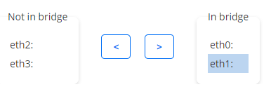
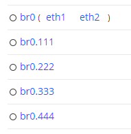
On the top-level Interfaces tab, a bridge will appear as shown in the following screenshot. Here, the bridge is called “br0”, and it bridges the interfaces “eth1” and “eth2”. VLANs have also been added to this bridge.
